How to Design a Photovoltaic(Solar) Power Station? A Step-by-Step Guide to Designing a Photovoltaic System
Photovoltaic (PV) power generation specifically refers to a power generation system that uses PV modules to directly convert solar energy into electricity.
It is a new and promising method for power generation and comprehensive energy utilization. It advocates the principles of generating electricity locally, connecting to the grid locally, and converting energy locally. This approach not only effectively increases the power generation capacity of PV power stations of the same scale but also resolves the issue of power loss during voltage boosting and long-distance transmission.
1 Cost Composition of Photovoltaic Power Generation System
A PV power generation system consists of modules, mounting structures, inverters, auxiliary materials, and construction. Among these, modules account for the majority of the cost, while mounting structures represent a smaller portion, as shown in the figure below.

2 Distributed photovoltaic power generation has the following characteristics:
Relatively Small Output Power
Generally, the capacity of a distributed PV power generation project is within a few kilowatts.
Unlike centralized power stations, the size of a PV power station has little impact on its power generation efficiency, and thus little effect on its economic viability. The return on investment for small-scale PV systems is not necessarily lower than that of large-scale systems.
Low Pollution and Significant Environmental Benefits
Distributed PV power generation projects produce no noise during operation and do not cause air or water pollution.
Can Partially Alleviate Local Power Shortages
However, the energy density of distributed PV power generation is relatively low, with a power output of only about 100 watts per square meter. Additionally, the limited roof area suitable for installing PV modules means it cannot fundamentally resolve power shortages.
Simultaneous Power Generation and Consumption
Large-scale ground power stations generate electricity by connecting to the transmission grid after voltage boosting, operating solely as power generation facilities. In contrast, distributed PV power generation connects to the distribution grid, allowing for simultaneous power generation and consumption, with an emphasis on local consumption.

3 Design principles
Introduction
The use of distributed photovoltaic systems is an effective means to achieve energy conservation and emission reduction. With the continuous development of technology, distributed photovoltaic systems have become increasingly mature. Relevant technical standards and specifications, such as GB/T 19939-2005 "Technical Requirements for Grid Connection of Photovoltaic Power Generation Systems" and GB/T 29319-2012 "Technical Requirements for Grid-Connected Inverters of Photovoltaic Power Generation Systems," provide technical support for the design, installation, and operation of distributed photovoltaic systems.
Safety
The design of distributed photovoltaic systems must comply with relevant national standards and industry regulations to ensure the safety of the system. Lightning protection and grounding design are crucial aspects to prevent damage to equipment and ensure personnel safety. The system's design must also consider environmental factors and operational safety to minimize risks.
Economic Benefits
The economic benefits of distributed photovoltaic systems are significant. By utilizing idle rooftops or open spaces for power generation, it reduces reliance on traditional energy sources, lowers electricity costs, and provides a stable return on investment.
Environmental Impact
Distributed photovoltaic power generation has minimal environmental impact. It helps reduce greenhouse gas emissions and air pollution, contributing to sustainable development and environmental protection.
Application Examples
In recent years, distributed photovoltaic systems have been widely applied in residential, commercial, and industrial settings across various regions. Successful case studies demonstrate their feasibility and effectiveness, providing valuable experience for future projects.
4 System design
Project Overview
This project utilizes approximately 30 m² of effective roof area, comprising 12 pieces of 260Wp PV modules. The mounting structure is made of aluminum alloy with a 30-year lifespan. The total installed capacity is 3.12KWp for a rooftop distributed PV power generation system.
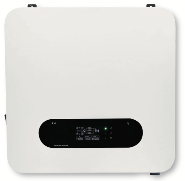
The system uses a 3KW Omnik PV inverter to convert DC power into 220V AC power, which is then connected to the 220V line leading to the owner's existing indoor distribution box. From there, it connects to the owner's low-voltage distribution network via a 220V line, enabling power delivery to the municipal grid.
Project Location
The project is located in Hong'an County, northeast of Hubei Province, on the southern slopes of the Dabie Mountains. It borders Macheng to the east, Dawu to the west, Huangpi (Wuhan) to the south, and Xinyang (Henan) to the north. The county is 80 km from the provincial capital, Wuhan.
The average frost-free period is 236.4 days per year. The average annual precipitation is 1,116.2 mm, with summer rainfall accounting for half of the total. The average annual snowfall is 8.3 days, the average relative humidity is 77%, and the average wind speed is 3 on the Beaufort scale. The average annual sunshine duration is 1,998.8 hours, accounting for 45% of the possible sunshine hours. The area is classified as a Class III solar resource region.
5 Photovoltaic(solar power) system design
PV(solar panel) Module Selection
This project uses 260P-60 polycrystalline silicon solar cell modules with a rated power of 260Wp.
PV Grid-Tied Inverter Selection
Since the project involves a residential distributed system with a grid connection voltage of AC220V, a single-phase PV inverter is selected.
Site Selection
For residential and household distributed PV power generation systems, the site is typically chosen on rooftops or open ground. Therefore, large-scale natural conditions (solar radiation, geographical location, transportation, water sources) and grid connection conditions (distance to the connection point, spacing of connection points, etc.) are not considered here.
Environmental factors more directly affect the site selection for residential and household distributed PV power generation systems. Key considerations include:
A. Presence of shading obstacles (both short-term and long-term)
B. Presence of salt damage or pollution
C. Winter snow, ice, lightning, and other hazards
For this project, the installation is on the owner's rooftop, with no tall buildings nearby, so no shadow analysis is required during the design layout.
Optimal Tilt Angle and Orientation for PV Arrays
To maximize the project's returns and simplify installation while ensuring aesthetic appeal, professional PV simulation software analysis indicates that the optimal solar tilt angle for this location is 26 degrees, facing due south.
This ensures the system's power generation is maximized over the annual cycle.
Considering factors such as PV mounting structure strength, system cost, and roof area utilization, the tilt angle is adjusted to reduce wind exposure, enhance structural strength, lower costs, and improve space utilization—without significantly reducing power generation (by no more than 1%).
The analysis suggests a recommended tilt angle of approximately 17 degrees (aligned with the roof's south-facing slope).
Optimal Spacing Between PV Arrays
To achieve the best annual power generation and maximize roof utilization, the spacing between PV arrays should prevent mutual shading between 9:00 AM and 3:00 PM on the winter solstice (December 22 or 23). This spacing is considered optimal.
Professional PV software simulation shows that with a tilt angle of 17 degrees and a minimum spacing of 5 meters between the lowest points of adjacent arrays, mutual shading is effectively avoided during the specified time on the winter solstice.
Series-Parallel Design for PV Arrays
In distributed PV power generation systems, solar cell modules are connected in series to form strings. Series connections increase the DC voltage of the system to match the inverter's input voltage range, ensuring the system operates within the inverter's limits under varying solar radiation and temperature conditions.
For this project, the inverter's maximum DC voltage (maximum array open-circuit voltage) is 550V, with a maximum power point tracking (MPPT) range of 70–550V and one MPPT channel per parallel connection.
Using 12 pieces of 260W polycrystalline silicon solar cell modules, each with a rated operating voltage of 31.2V and an open-circuit voltage of 38V, the preliminary design calls for 12 modules in series.
Under standard test conditions (25±2°C, 1,000 W/m² solar irradiance), the rated operating voltage of the 12-module string is 374.4V, and the open-circuit voltage is 456V, both within the inverter's allowable input range, ensuring normal operation.
Under varying conditions:
At an extreme low temperature of -10°C, the maximum power point voltage is 12 × 31.2 × (0.35% × 35 + 1) = 420.3V, meeting the 550V maximum MPPT input voltage requirement.
At an extreme high temperature of 42°C, the operating voltage is 12 × 31.2 × (-0.35% × 17 + 1) = 352.1V, meeting the 70V minimum MPPT input voltage requirement.
Accounting for a 2% system voltage loss, the design fully meets operational requirements.
After verification, the number of modules in series is confirmed as 12.
Electrical System Design
Based on the PV module selection, inverter selection, and series-parallel design, the electrical system for this PV power generation project is designed in accordance with the owner's low-voltage connection requirements.
Lightning Protection and Grounding Design
The basic components of a grid-connected PV power generation system include: the solar cell array, PV combiner box, box transformer, and inverter.
The mounting structure for the solar cell array is made of metal and occupies a large space, typically installed in open areas. During thunderstorms, it is particularly vulnerable to lightning strikes. Given the high cost of PV modules and inverters, effective lightning and surge protection is essential to avoid economic losses.
Key lightning protection measures for grid-connected PV power stations include:
External lightning protection devices such as lightning rods, strips, and nets to reduce the electromagnetic effects of lightning currents entering buildings and protect structures.
The PV equipment and building grounding systems are interconnected using galvanized steel, with anti-corrosion treatment at welding points. This reduces overall grounding resistance and creates an equipotential surface, minimizing overvoltages caused by lightning.
Horizontal grounding electrodes are buried at least 0.5 meters deep (below the frost line) and connected in a grid pattern using cross clamps. Underground connections must be wrapped with corrosion-resistant tape.
For this project, the lightning protection design includes external protection (grounding down conductors) and internal protection (surge protection).
Lightning Protection Design Description:
External protection: The metal components of the PV array (mounting structure, module frames, etc.) are connected to the existing rooftop lightning protection strip using horizontal grounding electrodes.
Internal protection: A Class II surge protector is installed between the neutral, live, and ground wires at the AC output of the grid-tied inverter. The surge protector's grounding terminal is connected to the grounding network (existing or newly installed) via horizontal grounding electrodes.
6 Revenue analysis
Key References:
Methods and Parameters for Economic Evaluation of Construction Projects (Third Edition) (issued by the National Development and Reform Commission and the Ministry of Construction in July 2006), State Council Notice on the Trial Implementation of a Capital System for Fixed Asset Investment Projects, and other relevant national policies.
Policies of Hubei Province.
National current loan interest rates, tax regulations, and related provisions.
Financial Evaluation
The total static investment for this project is ¥28,100, with a project life of 20 years (1-month construction period and 20-year operation period). The capital ratio is 100%, with the first year as the base year. The depreciation period is 20 years, with a residual value rate of 5%.
Other financial parameters are based on national regulations or industry standards.
Main Economic and Technical Indicators
| No. | Item | Unit | Value |
|---|---|---|---|
| 1 | Total Installed Capacity | kWp | 3.12 |
| 2 | 20-Year Cumulative Power Generation | kWh | 63,690 |
| 3 | Average Annual Power Generation | kWh | 2,81 |
| 4 | Maximum Power | kW | - |
| 5 | Annual Average Effective Utilization Hours | h | 4.7 |
| 6 | Average Annual Power Supply per Unit Area | kWh/m² | 1.69 |
| 7 | 20-Year Average Annual Power Supply | kWh | 6.39 |
| 8 | Equivalent Full Load Hours | h/kWh | 0.42 (20 years) |
| 9 | Average Electricity Cost per kWh | ¥/kWh | 0.25 (5 years) |
| 10 | Initial Investment per Unit Capacity | ¥/kWh | 0.567 |
| 11 | Annual Average Profit Margin | % | 3.58 |
| 12 | Internal Rate of Return | % | 6.37 |
Note: For small residential distributed power generation, the state exempts value-added tax (VAT).
This project has a total installed capacity of 3.12KWp, with a cumulative power generation of 63,690 kWh over 20 years. It operates in a "self-consumption with excess power fed to the grid" mode, with a self-consumption rate of 70%. The internal rate of return (IRR) on equity is 6.37%, and the payback period is 7.76 years.
7 Environmental Benefits
After completion, the 3.12KW PV power station will generate an average of 3,123 kWh annually (calculated over 25 years). Based on a theoretical coal consumption of 350g of standard coal per kWh for thermal power generation, the energy-saving and emission-reduction benefits are as follows:
Table: Environmental Impact Assessment Indicators
| Indicator | Unit | Value | Unit Conversion | Value | Standard Coal Equivalent (tce) | Emission Factor (25 t/Year) |
|---|---|---|---|---|---|---|
| Sulfur Dioxide Emissions (2007) | kgce/kWh | 0.35 | tce | 1.09 | 27.33 | |
| Distributed Photovoltaic System | kg/kWh | 1 | t | 3.12 | 78.08 | |
| Distributed Photovoltaic System | g/kWh | 3.35 | t | 0.01 | 0.26 | |
| CO₂ Reduction | g/kWh | 859.845 | t | 2.69 | 67.13 | |
| SO₂ Reduction | g/kWh | 8.03 | t | 0.03 | 0.63 |
Notes:
"kgce/kWh" is translated as "kgce per kWh" (kg of standard coal equivalent per kilowatt-hour).
"tce" stands for "ton of coal equivalent."
The values are translated as provided, with "t" representing metric tons and "g/kWh" as grams per kilowatt-hour.
The table structure and units are preserved for clarity and consistency.
The total investment for the 3.12KW rooftop distributed PV poverty alleviation project is ¥28,100, with an annual power generation of approximately 3,184 kWh and an annual revenue of about ¥3,200.
Therefore, distributed household PV systems not only offer stable investment returns and excellent energy-saving and emission-reduction effects but also effectively address income issues for low-income populations, achieving targeted poverty alleviation.
Room A612, Changhe Economic City, Nangang Science Park, Intersection Of Dabieshan Road And Tianlong Road, High-Tech Zone
Tel/Whatsapp/Wechat:+86 189 5600 2632
Email : info@jcvolt.com
Tel/Whatsapp/Wechat:+86 138 6669 4858
Email : kian.liu@solar-jc.com